
Eugene Wypior
SCADA Systems Defense in Depth Implementation

The design of an OT system is influenced by several factors such as control requirements, communication protocols, system reliability, and redundancy, which determine the type of topology to be used, such as SCADA, DCS, or PLC-based.
SCADA Systems Defense in Depth Implementation
Supervisory control and data acquisition (SCADA) systems are employed for controlling geographically dispersed assets where both centralized data acquisition and control are equally important. These systems are utilized in various distribution systems including water distribution and wastewater collection systems, oil and natural gas pipelines, electrical utility transmission and distribution systems, and rail and other public transportation systems. SCADA systems incorporate data acquisition systems with data transmission systems and human-machine interface (HMI) software to deliver a centralized monitoring and control system for multiple process inputs and outputs. The systems are designed to gather field information, transfer it to a control center, and present it to the operator visually or textually, thereby enabling the operator to monitor or control an entire system from a central location in nearly real-time. Depending on the complexity and configuration of the individual system, control of any specific system, operation, or task can be automated or executed by operator commands.
A typical SCADA system consists of a control server located at a central control center, along with communications equipment (e.g., radio, telephone line, cable, or satellite), and one or more remote field sites with remote terminal units (RTUs) and/or programmable logic controllers (PLCs) for controlling actuators and monitoring sensors. The control server processes the information received from the RTU inputs and outputs, while the RTUs or PLCs control the local process. Communication hardware enables the transfer of information between the control server and the RTUs or PLCs. The system software is programmed to monitor specific parameters and ranges and to initiate a response if a process variable falls outside the acceptable range. An intelligent electronic device (IED), such as a protective relay, may communicate directly with the control server, or a local RTU may poll the IEDs and collect the data, which is then passed to the control server. The IEDs provide a direct interface for controlling and monitoring equipment and sensors. SCADA systems are typically designed with fault-tolerant features and significant redundancy to ensure system availability, although this may not be enough to counter malicious attacks.
SCADA communication topologies vary among implementations.
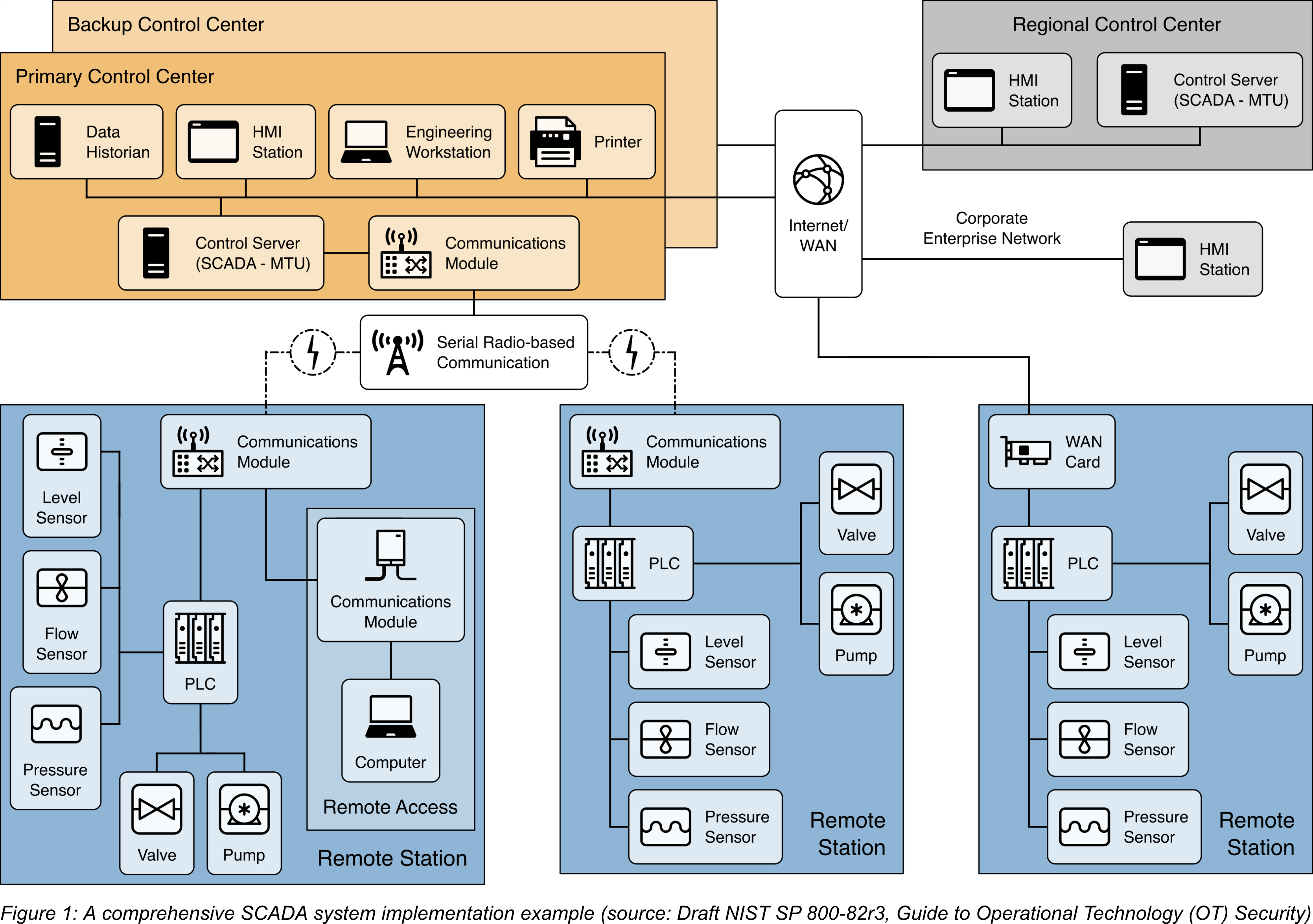
The figure below illustrates a sample implementation of a SCADA system. The system comprises a main control center and three field sites, with a backup control center for redundancy in case of a primary control center failure. Control center-to-field site communications use point-to-point connections, with two of the connections using radio telemetry. The third field site is local to the control center and uses the WAN for communication. A regional control center sits above the primary control center for additional supervisory control. The WAN provides corporate enterprise network access to all control centers, and field sites can be remotely accessed for maintenance and troubleshooting operations. The primary control center retrieves data from field devices at predefined intervals (e.g., 5 seconds, 60 seconds) and can transmit new set points to field devices as necessary. The control server not only polls and sends high-level commands but also monitors field site alarm systems for priority interrupts.
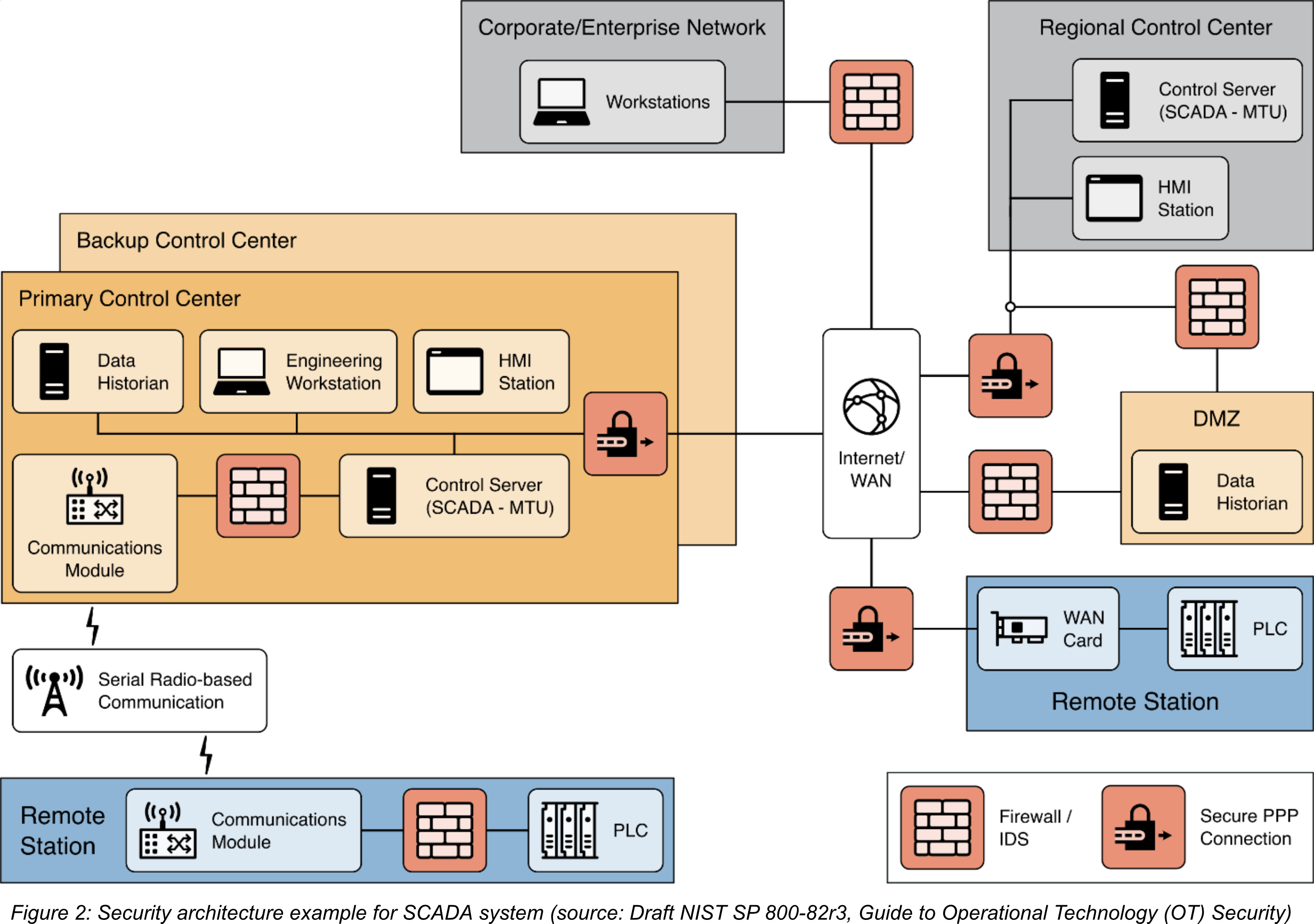
The following figure illustrates an example implementation of defense-in-depth for the SCADA system depictured above. It is assumed that the organization has already addressed the first two layers of security, namely Security Management and Physical Security. For the third layer, Network Security, the organization should consider implementing the following capabilities in the security architecture:
- To apply a defense-in-depth strategy in the SCADA environment, it is crucial to segregate networks into different zones or regions. The organization should also consider further segregation for security systems such as physical monitoring and access controls, doors, gates, cameras, VoIP, and access card readers.
- To control and monitor communications between the network segments, boundary devices such as firewalls should be added. Industrial-class stateful firewalls can provide more support for OT-specific protocols, which enhances protection for OT devices such as PLCs and controllers. Rules for inbound and outbound communication must be defined to ensure that only authorized communication is allowed to pass between the regions.
- To enhance security, secure connections such as VPN tunnels, encrypted channels, or point-to-point connections should be used between network segments, particularly for geographically distant locations. For example, such connections can be established between a regional center and primary control centers, and between remote stations and control centers. If required, these secure connections can be established over the Internet/WAN connection. Devices in the network segments should be restricted from accessing the Internet and should only connect to other segments through a secure connection.
- To apply a defense-in-depth strategy in the SCADA environment, it is important to implement a DMZ to isolate the control centers from the enterprise network. All communication between the enterprise network and the control centers should pass through services within the DMZ. However, since the DMZ is connected to outside environments, the services within it should be closely monitored and protected to prevent compromises that could allow attackers to pivot to the OT environment undetected.
To enhance hardware and software security in Layer 4 and Layer 5, organizations should adopt the principle of least functionality for all components in remote stations, control centers, and DMZ devices to support application and device hardening. The organization should disable any non-essential capability, software, or ports from the devices by identifying them. For example, some newer-model PLCs or HMIs may have a web server or SSH server capability that is not used. In such cases, those services should be disabled, and the associated TCP/UDP ports should also be disabled. The functionality should only be enabled when required.

0 Comments